
Jun 26, 2026News Center
How to Troubleshoot Optical Modules | Complete Guide for Stable Network Links
Learn how to troubleshoot optical modules step by step. Discover common causes of link failure, optical power issues, compatibility problems, and fiber troubleshooting tips.
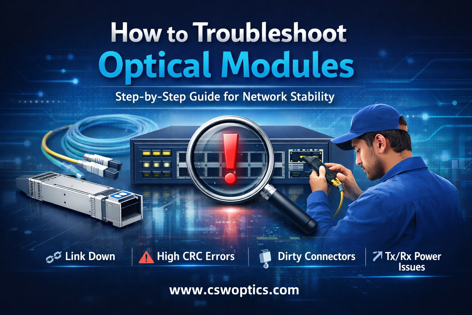
A Practical Guide for Stable and Reliable Network Connections
In modern enterprise networks and data centers, optical modules are responsible for one critical job: moving data quickly and reliably between devices.
But when a link suddenly goes down, packets start dropping, or interfaces show abnormal alarms, the optical module is often the first component engineers check.
The challenge is that many optical module problems look similar on the surface, while the real causes can be completely different.
A failed link may actually come from:
- Dirty fiber connectors
- Wrong wavelength pairing
- Excessive transmission distance
- Power budget mismatch
- Incompatible coding
- Switch firmware restrictions
- Poor-quality DAC/AOC cables
- Incorrect fiber polarity
- Overheating
- Or simply a loose connection
This guide explains how to troubleshoot optical modules step by step in a practical and easy-to-understand way.
Why Optical Module Troubleshooting Matters
When optical links become unstable, the impact is usually much bigger than a single disconnected port.
Problems can lead to:
- Network downtime
- Service interruption
- Slow application performance
- Packet loss
- Unstable VoIP or video traffic
- Storage synchronization failures
- Data center latency spikes
- Unexpected switch alarms
In many cases, engineers replace modules immediately without identifying the real issue. That increases maintenance cost and wastes troubleshooting time.
A systematic troubleshooting process helps teams:
✅ Find the root cause faster
✅ Reduce unnecessary module replacement
✅ Improve network stability
✅ Minimize downtime
✅ Extend hardware lifespan
Common Optical Module Problems
Before troubleshooting, it helps to understand the most common symptoms.
1. Link Down
The interface does not come up after the module is inserted.
Possible causes:
- Fiber disconnected
- TX/RX reversed
- Unsupported module
- Damaged transceiver
- Incorrect wavelength matching
- Distance exceeds module capability
2. Flapping Link
The interface repeatedly goes up and down.
Possible causes:
- Dirty connectors
- Weak optical power
- Overheating
- Unstable switch firmware
- Poor-quality compatible module
- Fiber bending or physical stress
3. High CRC or Packet Errors
The link stays up but traffic quality becomes unstable.
Possible causes:
- Optical signal degradation
- Excessive attenuation
- Fiber contamination
- Mismatched fiber type
- Low-quality patch cords
4. Unsupported Transceiver Alarm
Some switches reject third-party modules.
Common examples:
- Cisco unsupported transceiver warning
- EEPROM mismatch
- Vendor lock detection
- Security compatibility checks
5. Short Transmission Distance
The module works but cannot reach expected distance.
Possible causes:
- Wrong fiber type
- High insertion loss
- Low optical power output
- Connector quality issues
Step-by-Step Optical Module Troubleshooting Process
Step 1 — Check Interface Status
Always start from the switch CLI or device management interface.
Typical commands:
- show interface status
- show interface transceiver
- show logging
- diagnostic monitoring commands
Look for:
- Link state
- RX/TX optical power
- Temperature
- Voltage
- Current
- Error counters
These values often reveal whether the issue is physical or configuration related.
Step 2 — Verify Module Compatibility
Not all modules work with all switches.
Check:
- Speed compatibility
- Vendor coding
- Switch firmware version
- Required protocol support
For example:
- 10G SFP+ cannot work in a pure 1G port
- Some switches require coded EEPROM information
- Certain firmware versions block unsupported modules
Always confirm:
- Part number
- Transmission type
- Interface standard
- Distance specification
Original vs Compatible Optical Modules
Many enterprises today use both original and compatible optical transceivers depending on project requirements and budget.
Compatible modules can provide:
- Lower deployment cost
- Faster delivery
- Flexible customization
- Multi-brand interoperability
However, compatibility quality varies between suppliers.
Reliable suppliers usually perform:
- EEPROM coding validation
- Real switch testing
- DOM calibration
- Temperature stability testing
- Burn-in reliability tests
Step 3 — Inspect Fiber Connections
A surprisingly high percentage of optical issues come from dirty fiber connectors.
Even microscopic dust can significantly weaken optical signals.
Check for:
- Dust contamination
- Scratches
- Loose connectors
- Bent fiber
- Damaged patch cords
Best practices:
✅ Clean connectors before insertion
✅ Use fiber inspection tools
✅ Avoid excessive bending
✅ Keep dust caps installed when unused
Step 4 — Verify TX/RX Polarity
This is one of the most common installation mistakes.
Optical transmission requires:
- TX → RX
- RX → TX
If polarity is reversed, the link stays down even when both modules are functional.
This happens frequently with:
- LC duplex fiber
- MPO/MTP systems
- Structured cabling deployments
Step 5 — Check Optical Power Levels
Modern modules support Digital Optical Monitoring (DOM).
Key parameters:
- TX Power
- RX Power
- Temperature
- Voltage
If RX power is too low:
- Fiber attenuation may be excessive
- Distance may exceed module specification
- Connectors may be dirty
If RX power is too high:
- Short-distance links may overload receivers
- Attenuators may be required
Understanding Optical Power Budget
Optical modules are designed with specific transmission ranges.
For example:
Module Type | Typical Distance |
|---|---|
10G SR | 300m |
10G LR | 10km |
25G SR | 100m |
100G LR4 | 10km |
400G FR4 | 2km |
Using the wrong module type can easily create unstable links.
Step 6 — Test with Known Good Components
A fast way to isolate problems:
Replace one component at a time:
- Swap optical module
- Replace patch cable
- Change switch port
- Test another fiber path
This method quickly identifies whether the issue comes from:
- The module
- The switch
- The cable
- Or the fiber infrastructure
Step 7 — Monitor Temperature
Optical modules generate heat during operation.
Excessive temperature can cause:
- Link instability
- Signal degradation
- Premature failure
High-density switches especially require proper airflow.
Recommendations:
✅ Maintain proper rack ventilation
✅ Avoid blocked airflow
✅ Use industrial-grade modules in harsh environments
✅ Monitor DOM temperature regularly
Common Mistakes During Troubleshooting
Replacing Modules Too Early
Sometimes the real problem is simply:
- Dirty fiber
- Wrong polarity
- Bad patch cord
Replacing modules without diagnosis increases cost unnecessarily.
Ignoring Fiber Type
Different modules require different fiber types.
Examples:
- SR modules → Multimode fiber
- LR modules → Single-mode fiber
Incorrect pairing can cause severe signal loss.
Mixing Different Standards
Not all modules interoperate automatically.
Examples of problematic combinations:
- Different wavelength standards
- Different FEC requirements
- Incompatible breakout configurations
How to Reduce Optical Module Failures
Preventive maintenance is far more effective than emergency troubleshooting.
Recommended Best Practices
Use Qualified Optical Modules
Reliable modules should pass:
- Compatibility testing
- Environmental testing
- Optical calibration
- Long-term stability testing
Standardize Your Deployment
Using standardized module types simplifies:
- Inventory management
- Maintenance
- Troubleshooting
- Spare replacement
Maintain Proper Fiber Management
Good cable management reduces:
- Fiber stress
- Connector contamination
- Accidental disconnections
Monitor Network Health Proactively
Modern monitoring systems can detect:
- Optical power drift
- Temperature abnormalities
- Error rate increases
before complete failure occurs.
FAQ — Optical Module Troubleshooting
Why does my optical module show “unsupported transceiver”?
This usually happens because the switch firmware checks EEPROM vendor coding. Some devices restrict third-party modules unless properly coded.
Can dirty fiber connectors really cause link failure?
Yes. Even tiny dust particles can significantly reduce optical signal quality and cause packet loss or link instability.
Why is my optical link up but traffic unstable?
Common reasons include:
- Weak RX optical power
- Excessive attenuation
- CRC errors
- Poor fiber quality
- Overheating
How do I know whether the module or fiber is faulty?
The fastest method is component isolation:
- Swap module
- Replace patch cord
- Test another switch port
This helps identify the failing component quickly.
Do compatible optical modules work reliably?
High-quality compatible modules can perform very reliably when they are properly coded, tested, and validated for target switches.
Final Thoughts
Troubleshooting optical modules is not only about replacing hardware.
In many cases, the real issue comes from installation practices, fiber quality, compatibility mismatches, or environmental conditions.
A structured troubleshooting process helps network teams reduce downtime, improve reliability, and lower operational cost.
As networks continue evolving toward 100G, 400G, 800G, and even 1.6T architectures, stable optical connectivity becomes more important than ever.
Understanding how to diagnose and resolve optical module issues quickly is now a critical skill for modern network operations.
Need Reliable Optical Transceivers?
- Original optical transceivers
- Compatible optical modules
- DAC & AOC solutions
- Multi-brand coding support
- Fast delivery
- Customized solutions
- Enterprise and data center deployment support
Whether you need 10G, 25G, 100G, 400G, or next-generation high-speed optical solutions, our team can help you build stable and scalable networks.
👉 Contact us today to discuss your project requirements and compatibility needs.
optical module troubleshooting, transceiver troubleshooting, SFP troubleshooting, optical transceiver issues, fiber optic troubleshooting, compatible optical modules, optical power problems, network link failure, SFP module diagnostics, optical module compatibility